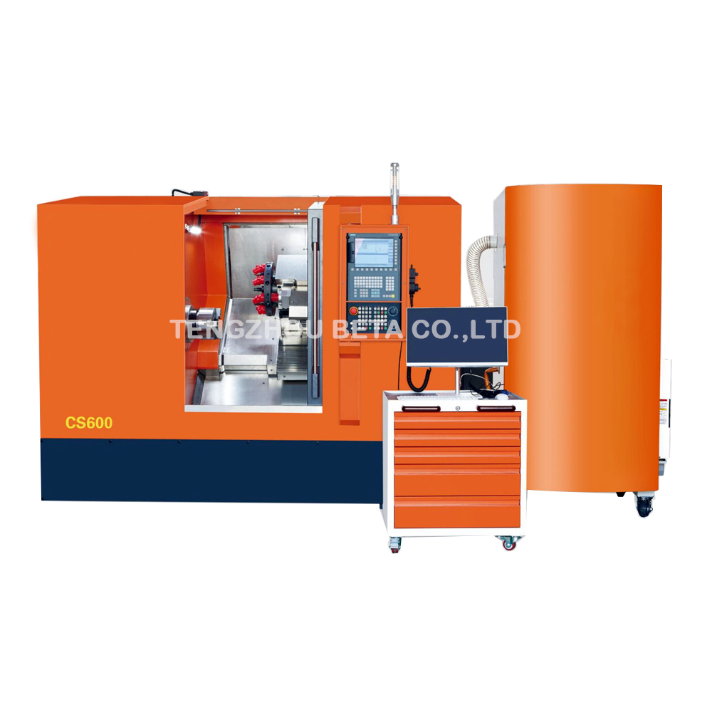
Precision manufacturing serves as the invisible backbone of our modern industrial landscape. It quietly shapes the mechanical world we interact with daily. From the intricate components inside commercial airliners to the robust drivetrain parts in electric vehicles, subtractive manufacturing has fundamentally revolutionized mass production. By systematically removing material from a solid block, engineers achieve microscopic tolerances and unwavering repeatability at a massive scale.
At the absolute core of this industrial evolution is Computer Numerical Control, widely known as CNC, turning. Recognized as a highly efficient machining process, it is the go-to methodology for creating flawless cylindrical parts. The driving force behind this subtractive method is the lathe. This powerful equipment seamlessly marries centuries-old turning principles with cutting-edge computerized automation.
This comprehensive guide breaks down the entire turning workflow from start to finish. We will explore the specific operations performed on the shop floor and dissect the mechanical anatomy of these machines. Furthermore, we provide actionable insights to help you make informed procurement decisions for your manufacturing facility.
Key Takeaways
Process Efficiency: Operating as a highly optimized subtractive manufacturing method, this process relies on rapidly rotating a workpiece while a stationary cutting tool systematically shaves away material. It remains the undisputed champion for producing precise cylindrical components.
Machine Anatomy: The foundational equipment relies on a rigid kinematic chain. Critical elements include the high-torque main spindle, the hydraulic workholding chuck, the rapid-indexing tool turret, and the sophisticated computerized control unit.
Versatile Operations: Modern turning centers are engineered for extreme versatility. A single setup can execute a sequence of complex cuts, including straight turning, facing, deep grooving, internal boring, threading, and final parting.
Industry Applications: Providing unmatched dimensional accuracy, this technology scales effortlessly across sectors. Applications range from heavy-duty aerospace turbine shafts to specialized polymer processing, offering lucrative solutions for facilities upgrading their production infrastructure.
What is CNC Turning?
To truly grasp the mechanics of this highly precise subtractive manufacturing method, it helps to contrast it with its counterpart, CNC milling. Walking across a modern shop floor, you will notice that in a milling operation, the cutting tool spins aggressively while the metal block remains firmly clamped to a stationary table. In contrast, CNC turning reverses this physics. The raw material itself is firmly gripped and rotated at blistering speeds. Meanwhile, a single-point cutting tool remains relatively stationary, advancing smoothly along specified linear axes to peel away layers of material.
The primary piece of equipment utilized to execute this metal removal is the precision CNC turning lathe machine. By leveraging computerized commands, these advanced systems completely eliminate the manual hand-wheel adjustments that plagued traditional engine lathes. This digital oversight results in superior accuracy and drastically reduced cycle times. It also eliminates human error during complex geometric cuts.
Specifically, this process boasts incredible versatility regarding material compatibility. Fabrication shops frequently turn a vast array of rigid alloys, including 6061 aluminum, 304 stainless steel, carbon steel, brass, and high-strength titanium. Beyond traditional metals, the turning process is highly effective for machining engineering plastics. Materials like PTFE, commonly known as Teflon, Nylon, and polyurethane are regularly shaped into specialized fluid control components and industrial seals.
Step-by-Step: The CNC Turning Process
The transformation from a raw, rough-cut billet of metal into a gleaming, high-tolerance component is not accidental. It requires a strict, sequential workflow. Understanding these distinct phases is crucial for optimizing production efficiency and keeping scrap rates to an absolute minimum.
CAD Design and CAM Programming
Every physical part begins its life in the digital realm. Mechanical engineers utilize Computer-Aided Design software to draft an exact two-dimensional profile or a comprehensive three-dimensional model of the desired component. Once the design clears engineering approvals and tolerances are strictly defined, the digital file is imported into Computer-Aided Manufacturing software.
This software acts as a vital translator. It converts digital geometry into G-code and M-code, which is the alphanumeric language the machine natively understands. G-code dictates the precise geometric toolpaths, such as rapid positioning and circular interpolation. Meanwhile, M-code commands the hardware to perform actions like activating the high-pressure coolant pump or engaging the spindle motor.
Machine Setup and Workholding
Before the automated machining cycle can commence, a skilled operator must prepare the physical equipment. This tactile phase involves loading the raw bar stock into the machine workholding device, typically a hydraulic chuck or a precision collet. Proper workholding is an absolute engineering necessity. The operator ensures the material is secured with adequate clamping force to prevent it from slipping or vibrating during high-speed rotation. This vibration phenomenon is known as chatter. Chatter is the enemy of surface finish. Excessive vibration inevitably leads to poor, cloudy surface finishes and rapid degradation of the cutting tools.
Tool Loading and Offsets
Because complex geometries require a variety of cutting profiles, operators meticulously load specific tools into the machine indexing turret. A standard setup might include aggressive roughing inserts, sharp finishing tools, specialized grooving blades, and carbide drills.
Once physically installed, the operator must calibrate the tool offsets. Using a delicate touch-off probe or manual measurement techniques, the machine control unit is taught the exact spatial coordinates of each tool cutting tip relative to the workpiece. Without this microscopic calibration, achieving tight dimensional tolerances would be impossible.
Executing the Machining Cycle
With the program verified, material clamped, and tools calibrated, the operator presses cycle start. The automated process typically follows a two-stage cutting strategy. First, the distinct, aggressive sound of roughing passes fills the air. The machine utilizes a high feed rate and a deep depth of cut to aggressively shear away bulk material, leaving the part just slightly oversized. Immediately following this, a sharper finishing tool indexes into position. The machine lowers the feed rate, increases the spindle RPM, and takes a delicate final pass to shave off the last few thousandths of an inch, revealing a mirror-like surface finish.
Core CNC Turning Operations
Modern turning centers are engineered for remarkable operational flexibility. They can execute a wide variety of specialized cuts without ever requiring the operator to unclamp the part. This maintains perfect concentricity from start to finish.
Facing and Straight Turning
Facing is almost always the inaugural operation performed on a fresh piece of stock. The cutting tool moves radially across the exposed end of the rotating workpiece, shaving off the rough, saw-cut edge to create a perfectly flat surface. This pristine face serves as the zero-reference point for all subsequent measurements. Following this, straight turning takes over. The tool moves axially, parallel to the rotation of the workpiece, peeling material from the outer diameter to reduce the stock to its specified cylindrical dimension.
Tapering and Chamfering
Instead of moving strictly parallel or perpendicular, tapering requires the tool to move simultaneously along both the radial X and axial Z axes. This synchronized, diagonal movement creates a smooth conical shape. Chamfering, on the other hand, involves cutting a small angled edge, typically 45 degrees, at the sharp corner of a cylinder. From a practical standpoint, chamfers are essential for removing dangerous burrs and facilitating easier assembly when the part is later inserted into a mating hole.
Grooving and Parting
When a design calls for seating an O-ring or a retaining clip, grooving is employed. A specialized, square-nosed form tool plunges directly into the side of the spinning workpiece to cut a narrow, precise channel. Once all other features are completed, the parting operation concludes the cycle. A thin, blade-like tool plunges radially into the material until it breaches the center axis, neatly severing the finished component from the remaining bar stock.
Boring, Drilling and Threading
While turning traditionally focuses on the outer diameter, utilizing a CNC turning lathe machine for internal operations is equally critical. A stationary drill bit can be driven into the center axis to create an initial hole. Subsequently, a rigid boring bar is inserted into that pre-drilled cavity to enlarge its diameter and ensure absolute straightness. Finally, by synchronizing the spindle rotation with the tool linear feed rate, the machine can cut precise helical grooves to create internal or external screw threads.
The Anatomy of a CNC Lathe Machine
Evaluating capital equipment requires a deep understanding of its underlying hardware. The rigidity, thermal stability, and mechanical precision of these core components directly dictate the quality of the parts rolling off the production line.
The Spindle and Chuck
The main spindle acts as the core driver of the machine. Driven by a high-torque electric servomotor, it provides the immense rotational force necessary to spin heavy workpieces against resistant cutting tools. Spindles are cradled by high-precision angular contact bearings to minimize runout or wobble. Bolted to the spindle nose is the chuck, a heavy mechanical clamping device that typically utilizes three hydraulically actuated jaws closing simultaneously to center and grip the raw material with crushing force.
The Tool Turret
To minimize non-cutting time, machines utilize an automated tool turret. This indexing carousel holds multiple cutting tools, commonly 8, 10, or 12 stations. Driven by rapid servo motors, the turret can unclamp, rotate to a new tool station, and rigidly lock back into place in a fraction of a second. This ensures a seamless transition between different machining operations.
The Tailstock and Bed
When machining long, slender shafts, the sheer force of the cutting tool can cause the material to deflect or bend. To counteract this, a tailstock is positioned on the opposite end of the main spindle. It extends a rotating live center to support the free end of the workpiece, ensuring rigidity across the entire length of the cut. Supporting all of this is the machine bed. Cast from heavy-duty iron or polymer concrete, the bed absorbs high-frequency vibrations and resists thermal expansion, providing a massive, stable foundation for the linear guideways.
The CNC Control Panel
Serving as the central nervous system and the Human-Machine Interface, the control panel consists of a ruggedized screen and a specialized keypad. Operators stand at this console to load G-code programs, adjust microscopic tool offsets, monitor spindle loads in real-time, and manually jog the machine axes. Industry-standard control systems ensure the machine executes commands with zero latency.
Types of CNC Turning Lathe Machines
Machine tool builders offer various configurations to accommodate specific part geometries, facility footprints, and production volumes. Selecting the right architecture is critical for long-term operational success.
Machine Type
Spindle Orientation
Best Suited For
Key Engineering Advantage
Horizontal Lathe
Parallel to the floor
Standard shafts, fittings, and general cylindrical parts.
Highly versatile, easy to integrate with automated bar feeders for high-volume runs.
Vertical Lathe
Perpendicular to the floor
Massive pump housings, aerospace turbine disks, heavy gear blanks.
Leverages gravity to stabilize exceptionally heavy or large-diameter parts safely.
Swiss-Type Lathe
Horizontal with guide bushing
Medical bone screws, aerospace firing pins, micro-components.
Eliminates material deflection by supporting the workpiece exactly at the cutting point.
Current Industry Trends in CNC Turning
The machining landscape is currently undergoing a massive paradigm shift driven by smart factory initiatives. Today, manufacturers are moving away from isolated equipment and embracing fully connected ecosystems. The integration of the Internet of Things allows modern equipment to stream real-time data regarding spindle vibration, tool wear, and thermal fluctuations directly to cloud-based dashboards. This enables predictive maintenance, where algorithms alert operators to change a bearing or a cutting insert before a catastrophic failure occurs.
In addition, there is a distinct industry trend toward specialized non-metal machining. As global demand for advanced fluid control systems rises, standard metal-cutting lathes often struggle with the thermal dynamics of industrial plastics. Consequently, facilities are investing heavily in purpose-built equipment optimized for polymer processing. These specialized machines feature customized spindle speeds and advanced chip evacuation systems to prevent plastic melting and ensure pristine surface finishes, directly addressing the pain points of high scrap rates in seal manufacturing.
Industrial Applications: What Can You Make?
The inherent accuracy and repeatability of this technology make it a foundational process across nearly every sector of the global supply chain. In general manufacturing, job shops rely on turning centers to churn out everyday mechanical components, including custom threaded fasteners, brass bushings, hydraulic fittings, and aluminum spacers.
The stakes are significantly higher in the automotive and aerospace sectors. These industries demand strict adherence to microscopic tolerances and the ability to machine notoriously tough superalloys. Turning is heavily utilized to manufacture critical engine valves, transmission gears, landing gear struts, and high-strength titanium fasteners that must withstand extreme stress and drastic temperature fluctuations without failure.
Beyond standard metals, there are highly specialized applications, particularly in fluid control systems. The production of industrial seals, custom O-rings, and hydraulic wipers requires machining specialized, flexible polymers without tearing or deforming the material. Facilities operating in this lucrative niche often invest in highly specialized equipment, such as a CNC turning lathe machine for seal making. These units are specifically calibrated to handle the unique cutting dynamics, low-heat requirements, and stringent surface finish demands of industrial plastics.
Buying Guide: How to Choose the Right CNC Lathe Machine
For manufacturing executives and procurement engineers, selecting the correct machinery is a high-stakes decision. The right machine optimizes workflow and boosts profit margins, while the wrong specification can lead to endless production bottlenecks.
Size, Swing, and Processing Diameter
A machine must physically accommodate your largest anticipated parts. Buyers must evaluate the chuck size and the maximum processing diameter. For example, when processing large industrial seals, a machine offering a 500mm maximum processing diameter, such as the CS500 precision CNC turning lathe machine, provides the exact spatial capacity required without the massive footprint of a heavy-duty oil country lathe. Matching the machine capacity to your specific product line prevents overspending on unnecessary size.
Control Systems and Motor Power
The brain and muscle of the machine dictate its performance. Look for industry-proven control systems, like the SYNTEC controller, which offer high-speed processing and intuitive interfaces for operators. Furthermore, evaluate the servo motor power. A robust 4.4kW servo motor ensures the spindle maintains consistent torque even during aggressive roughing passes or when machining tough, friction-heavy polymers.
Number of Axes and Tooling Capacity
The most fundamental decision revolves around the axis configuration. Standard 2-axis machines operate purely on the radial X and axial Z axes. They are cost-effective, robust, and perfect for purely cylindrical parts. Conversely, advanced multi-axis turning centers incorporate live tooling to perform milling operations directly on the lathe. Additionally, consider the tool post. An 8-station or 12-station automatic turret drastically reduces setup times compared to manual tool posts, allowing for continuous, uninterrupted machining cycles.
Budget and Return on Investment
Procurement teams must carefully balance the initial Capital Expenditure against long-term Operational Expenditure. While a high-end turning center requires a substantially higher upfront investment, it significantly reduces setup times, minimizes work-in-progress inventory, and lowers the risk of human error. Calculating an accurate Return on Investment should factor in these long-term efficiency gains, reduced labor hours, and expected reductions in scrapped material.
Conclusion
Computer Numerical Control turning stands as a highly essential and transformative subtractive manufacturing process. By efficiently shaping raw materials into complex, high-tolerance components, it supports the infrastructure of countless modern industries. Investing in the proper equipment is not merely a capital expense. It is a direct upgrade to your overall production capabilities, dictating the speed, quality, and profitability of your output.
Whether you are machining simple aluminum standoffs on a standard lathe or turning complex polymer seals on specialized equipment, understanding the underlying machinery empowers businesses to optimize their workflows. Carefully evaluate your specific part dimensions, material requirements, and daily volume targets before making a purchase.
We encourage facility managers and procurement engineers to assess their current production bottlenecks. To explore equipment tailored to your specific production needs, from heavy metal cutting to precision polymer processing, visit BetaCNC to find the perfect machinery for your shop floor. Finding the ideal equipment solution ensures long-term profitability and unwavering product quality in an increasingly competitive manufacturing landscape.
Frequently Asked Questions
What is the difference between a CNC lathe and a CNC turning center?
While the terms are frequently used interchangeably on the shop floor, there is a distinct technical difference. A basic CNC lathe typically operates strictly on two axes, X and Z, and is designed solely for standard turning operations. A CNC turning center is a more advanced, robust machine that includes additional capabilities such as live tooling, Y-axis milling capabilities, and sometimes secondary sub-spindles. This allows a turning center to perform combined turning and milling operations in a single, uninterrupted setup.
What materials can be machined on a CNC turning lathe machine?
These machines are incredibly versatile and possess the rigidity to cut almost any solid material. Common metals include aluminum, various grades of stainless steel, carbon steel, brass, copper, and specialized aerospace alloys like titanium and Inconel. Additionally, they are widely used to machine industrial plastics such as PTFE, Delrin, nylon, and polyurethane, provided the correct cutting speeds and sharp tooling are applied.
How accurate is a CNC lathe machine?
Modern CNC equipment is engineered for exceptional, repeatable precision. Depending on the machine build quality, thermal stability, and operating environment, standard industrial lathes can often hold tolerances as tight as plus or minus 0.0005 inches. Specialized equipment, such as Swiss-style lathes, can achieve even tighter, microscopic tolerances, ensuring high repeatability across mass production runs of thousands of parts.
Can a CNC lathe perform milling operations?
Yes, but only if the machine is specifically equipped with a feature known as live tooling. Live tooling allows the machine turret to hold powered rotary tools, such as end mills or drill bits. The main spindle can lock the workpiece in a specific orientation using a C-axis, while the live tools cut flats, keyways, or cross-holes into the part, effectively combining the capabilities of a lathe and a mill into one machine.
How much does a CNC turning machine cost?
The cost varies drastically based on size, capabilities, and brand. Entry-level, 2-axis machines for small workshops can start around twenty thousand to thirty thousand dollars. Mid-range industrial lathes typically range from fifty thousand to one hundred thousand dollars. High-end, multi-axis turning centers with live tooling, sub-spindles, and robotic automation can easily exceed two hundred and fifty thousand dollars. Buyers must weigh the initial cost against the projected production volume and part complexity.
What is the difference between 2-axis and 3-axis CNC turning?
A 2-axis lathe moves the cutting tool along two linear directions: the X-axis controls the diameter of the part, and the Z-axis controls the length. It is perfect for standard cylindrical shapes. A 3-axis lathe introduces a C-axis or Y-axis. The C-axis allows the main spindle to stop and rotate to precise angles, enabling live tooling to drill off-center holes or mill flat surfaces on the cylindrical part without moving it to a separate milling machine.
TENGZHOU BETA CO.,LTD is located in Tengzhou City, Shandong Province. Our company is a professional manufacturer and exporter of machine tool equipments and accessories.