

Views: 0 Author: Site Editor Publish Time: 2026-11-19 Origin: Site


Many machine shop owners and manufacturing engineers face significant confusion when navigating the capital equipment market for a new CNC turning center. Machine tool builders frequently use the term "slant bed" loosely in their brochures. This marketing tactic often leads to costly misunderstandings and mismatched equipment on the shop floor.
An angled configuration is highly desirable for modern machining due to its ergonomic and operational benefits. However, empirical evidence from the shop floor shows that not all slant beds are created equal. The industry fundamentally divides these machines into the True Slant bed and the Flatbed Flying Wedge. The latter is essentially a bolt-on mechanical workaround.
Understanding the structural, thermal, and performance differences between these two foundational designs is critical. This knowledge forms the basis of a sound purchasing decision. This breakdown explores the engineering principles behind both structural architectures. It provides objective data to help you choose the right equipment based on your specific manufacturing needs, part tolerances, and budget constraints.
True Slant Beds are cast as a single, solid piece of angled iron. They offer superior structural rigidity, thermal stability, and natural gravity-assisted chip evacuation.
The Flying Wedge is technically a flat bed machine equipped with an angled saddle. This saddle is bolted onto the cross-slide to mimic a slant bed configuration.
A True Slant bed provides maximum precision for high-speed, high-volume production. Consequently, it requires a significantly higher capital investment.
A flat bed design remains highly cost-effective. It offers excellent stability for heavy, large-diameter turning applications while being easier to manufacture.
Knowing how to physically identify a true slant versus a flying wedge will protect your investment. This ensures your machinery meets your actual operational expectations.
The bed serves as the foundational spine of any turning center. It is the primary structural component supporting the headstock, tailstock, carriage, and turret. Every ounce of cutting force generated during the machining process transfers through the tool directly into the machine base. Therefore, the base design dictates overall performance, accuracy, and machine longevity. A poorly designed foundation will compromise precision regardless of how advanced the control system or spindle motor might be.
The geometry and mass of the cast iron structure heavily impact vibration damping, tool life, and surface finish. In turning operations, the physical distance between the cutting tool tip and the linear guideways is known as the moment arm. A well-designed casting minimizes this moment arm. This reduction decreases the leverage forces that cause chatter during aggressive roughing. Furthermore, a continuous, heavy cast iron matrix absorbs resonant frequencies before they reflect back into the cutting zone. This structural damping translates directly to extended carbide insert life and superior dimensional accuracy on the final workpiece.
A true slant bed features a base that is poured and cast at a distinct angle in the foundry. The defining characteristic of this design is its monolithic structure. From the floor up to the guideways, it is one continuous, uninterrupted piece of heavy-duty cast iron like Meehanite. There are no structural joints, seams, or bolted-on risers between the primary machine base and the linear rails. This seamless construction ensures unparalleled structural integrity under heavy cutting loads.
Manufacturers engineer true slant beds at specific incline angles. Each angle serves a distinct engineering purpose:
30-Degree: Often utilized for massive, heavy-duty lathes. It keeps the center of gravity lower to the ground while providing better chip flow than a purely horizontal surface.
45-Degree: The industry standard for general CNC turning. It offers the optimal balance between gravitational chip evacuation, operator ergonomics, and machine footprint.
60-Degree: Found on ultra-compact machines or specialized high-production turning centers. This steep angle minimizes floor space and ensures maximum vertical chip fall. It is ideal for automated robotic loading cells.
Structural analysis highlights three primary mechanical benefits of the single-piece slant bed. First, it provides gravity-assisted chip evacuation. Stringy chips and hot coolant fall naturally straight down into the conveyor. This prevents thermal buildup around the workpiece. Second, the slanted design brings the spindle and heavy chuck closer to the operator. This improves ergonomics and reduces lower back strain during manual part loading. Finally, the angled geometry ensures that the primary downward and backward cutting forces are directed straight into the thickest part of the casting. This effectively neutralizes harmonic vibration.
The Flying Wedge design is an engineering compromise. It was developed to offer slant-bed features on a traditional horizontal architecture. In this configuration, manufacturers take a standard Flat Bed CNC Lathe and bolt an angled wedge onto the flat cross-slide. The tool turret is then mounted to this angled adapter. Visually, the working envelope looks identical to a true slant machine. However, the underlying mechanics rely on a bolted joint rather than a single solid casting.
The primary driver behind the flying wedge is manufacturing economics. Casting, machining, and grinding a horizontal flat bed is geometrically simpler. It is significantly less expensive than producing a monolithic 45-degree angled casting. The foundry molds are less complex, and machining the base requires less specialized equipment. By utilizing a bolt-on wedge, machine tool builders can provide shops with slant bed features at a much lower price point. This appeals directly to budget-conscious buyers.
Buyers must exercise extreme caution. Many flying wedge machines are marketed broadly across the industry as slant bed lathes. The turret does indeed sit at an angle, but applying this terminology to a bolted-on wedge is technically misleading. Understanding this distinction is vital. The structural behavior of a bolted assembly under heavy cutting loads is fundamentally different from that of a single-piece cast bed.
Feature |
True Slant Bed |
Flatbed "Flying Wedge" |
Traditional Flat Bed |
|---|---|---|---|
Casting Structure |
Single monolithic angled piece |
Flat base with bolted angled saddle |
Single monolithic horizontal piece |
Rigidity & Vibration |
Exceptional damping, no weak joints |
Moderate; bolted joint can cause chatter |
High stability, excellent for heavy loads |
Thermal Stability |
Uniform heat dissipation |
Uneven expansion at the bolted joint |
Consistent, but chips may pool heat |
Chip Evacuation |
Excellent; gravity-assisted vertical drop |
Poor; chips nest on the flat slide below |
Moderate; requires manual or coolant wash |
Cost Investment |
Premium pricing |
Mid-range pricing |
Highly cost-effective |
Structural integrity is the most critical differentiator. A true slant bed relies on continuous cast iron to absorb cutting forces, offering maximum static and dynamic stiffness. In contrast, a flying wedge introduces a mechanical bolted joint between the carriage and the bed. In structural engineering, any joint is a potential weak point where micro-movements can occur. During aggressive roughing cuts or interrupted turning, this interface magnifies harmonic vibrations. This leads to reduced rigidity and chatter marks on the machined part.
Thermal dynamics play a massive role in machining accuracy. As a machine runs, the spindle, ballscrews, and cutting action generate intense heat. A true slant bed acts as a single mass, absorbing and dissipating this heat evenly. Conversely, in a flying wedge design, the bolted joint acts as a thermal barrier. The wedge and the flat bed below it heat up and expand at different rates. This uneven thermal expansion causes the tool center to drift during long cycle times. Operators are then forced to make frequent offset adjustments.
On a true slant bed, the path from the cutting tool to the chip pan is completely unobstructed. Chips fall directly down. On a flying wedge machine, the turret is angled, but the bed directly beneath the wedge remains completely flat. Consequently, chips fall off the workpiece only to nest and accumulate on the flat ways or cross-slide below. This accumulation causes localized heat buildup, blocks coolant flow, and interferes with the mechanical movement of the telescopic way covers.
Recent market analyses highlight a distinct bifurcation in CNC lathe procurement trends. Sectors like aerospace, medical device manufacturing, and electric vehicle production demand tighter tolerances on exotic alloys. Materials like Inconel and titanium require ultra-rigid, true slant architectures. These high-stress applications necessitate the superior thermal stability and vibration damping that only a monolithic casting provides.
Simultaneously, the broader subcontracting and job shop market is experiencing a renaissance in traditional flatbed adoption. Facilities are realizing that over-capitalizing on high-end slant beds for general-purpose turning erodes profit margins. Cost control is driving a return to modernized flatbed designs. Builders are upgrading flatbeds with advanced linear guideways and improved control systems. This bridges the gap between affordability and high performance. Manufacturers no longer default to slant beds. They strategically align the machine's structural DNA directly with their specific production volume and part geometry.
It is an objective reality that not every manufacturing facility requires the ultra-high performance of a monolithic slant bed. A traditional Flat Bed CNC Lathe offers substantial capital cost savings. For job shops, prototyping labs, maintenance departments, or environments running low-volume production batches, this design provides a rapid return on investment. You avoid over-capitalizing on structural rigidity that your specific parts do not demand.
Flat beds excel in specific heavy-duty applications. Their wide horizontal stance, parallel guideways, and exceptionally low center of gravity provide a highly stable platform. This makes them ideal for turning massive, heavy, and extremely long workpieces. Industries dealing with large oil pipes, heavy hydraulic cylinders, or massive power generation shafts consistently prefer the grounded, load-bearing stability of a flat bed architecture.
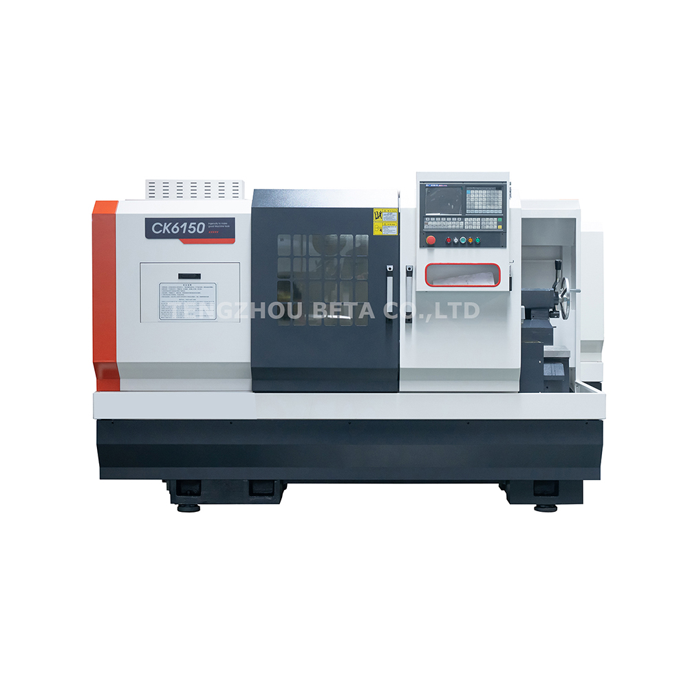
For buyers seeking a strategic balance of accessible pricing and reliable performance, exploring dedicated flat bed models is a prudent step. When evaluating equipment, look for specific parameters that guarantee rigidity. For instance, the CK6150 Flat Bed CNC Lathe features a generous 500mm swing over bed and a hardened cast iron base. Wide rectangular guideways ensure optimal load distribution across the X and Z axes. Machines in this category deliver powerful cutting capabilities and high torque for large-diameter parts, all without the premium capital investment required for a true slant bed turning center.
The most definitive way to identify a machine's true architecture is to look beneath the telescopic way covers. Grab a flashlight and inspect the base. If the linear rails or box ways are mounted directly to a massive, angled piece of cast iron that extends continuously down to the leveling pads on the floor, you are looking at a true slant bed. Conversely, if the primary guideways are mounted to a horizontal flat surface, and an angled iron block is simply bolted on top of the cross-slide, it is a flying wedge.
Observing the kinematics of the machine provides another clear clue. On a true slant bed, the entire X-axis carriage moves diagonally along the angle of the bed casting. On a flying wedge design, the base X-axis carriage typically moves horizontally across the flat bed. Only the static turret assembly itself sits at a permanent angle above the horizontal plane.
Selecting the correct bed design requires a critical analysis of your specific operational data. Use this simple engineering matrix. If your shop runs continuous high-volume production cycles, machines tough aerospace materials, and requires holding tight tolerances under 0.0005 inches over 24-hour shifts, a True Slant Bed is the necessary choice. On the other hand, if your operations involve medium volume runs, large diameter parts, easily machinable materials, or strict budget limits, a high-quality Flat Bed CNC Lathe will provide exceptional performance and better profit margins.
Ultimately, the decision comes down to the total cost of ownership. A true slant bed requires a higher upfront capital expenditure. Empirical data suggests it pays for itself over time through extended tool insert life, reduced scrap rates from thermal drift, and less machine downtime. A flat bed is cheaper to acquire and offers a faster initial return on investment for general machining tasks. This makes it a highly practical and profitable choice for growing machine shops upgrading from manual lathes.
Choosing the right bed design fundamentally impacts your machining success and shop floor profitability. True slant beds offer maximum rigidity, thermal stability, and chip evacuation for high-volume, high-precision production. In contrast, traditional flat beds provide a budget-friendly, highly stable alternative engineered specifically for large diameter turning and heavy-duty applications. Always inspect the bare casting to verify the machine's true structure. Match the lathe specifications directly to your production needs rather than marketing brochures. To explore robust and cost-effective turning solutions tailored to your operational requirements, discover the full range of professional equipment at BetaCNC and secure the right foundation for your manufacturing future.
The primary advantages are superior structural rigidity derived from a single-piece casting, excellent gravity-assisted chip evacuation, and enhanced thermal stability. These factors empirically result in higher machining precision, better surface finishes, and significantly longer cutting tool life.
Not necessarily. A flat bed machine delivers immense accuracy, especially when turning large, heavy workpieces. Its low center of gravity provides exceptional load-bearing stability. However, for high-speed, continuous production where thermal expansion and harmonic vibration are major factors, a true slant bed maintains its volumetric accuracy better over long, uninterrupted cycles.
Tool life is directly tied to vibration damping. A monolithic slant bed absorbs the harmonic frequencies generated during cutting, preventing micro-chatter at the tool tip. Bolted joints, like those found in flying wedge designs, can amplify these vibrations, which prematurely chips or wears down carbide inserts.
True slant beds are generally superior for automated bar feeding operations. The angled design allows continuous, stringy chips to fall directly into the chip conveyor without operator intervention. Flat beds can allow chips to accumulate around the chuck, which may interfere with automated part catchers or bar pullers during unattended machining.
Because the turret sits at an angle, the machine visually resembles a slant bed and offers similar ergonomic benefits for the operator. Manufacturers frequently use the term slant bed for marketing purposes to appeal to modern buyers, even though the foundational casting is technically a traditional horizontal flat bed.
Yes. Traditional flat beds are often the preferred architecture for ultra-heavy-duty turning applications, such as machining massive shafts, oil pipes, and large cylinders. Their wide, flat base provides an incredibly stable center of gravity that safely supports exceptionally heavy load capacities without deflection.
While pricing structures vary by linear guide type and machine size, a true slant bed CNC turning center is generally 20 to 40 percent more expensive than a comparable flying wedge or flat bed machine. This price premium reflects the increased foundry costs, mold complexity, and sheer weight of the single-piece angled cast iron.


